
Variable Frequency Oscillator Using Direct Digital Synthesis#
Introduction#
Credit for this design goes to Richard Visokey, callsign AD7C.
In this project, we will build a variable frequency oscillator using the AD9850 Direct Digital Synthesis (DDS) module. The AD9850 is a highly integrated device that uses advanced DDS technology to generate a stable and accurate frequency output. The module can generate frequencies from 0 to 40 MHz with a resolution of 1 Hz. The AD9850 module is controlled via a serial interface, which allows for easy integration with microcontrollers and other digital devices.
The AD9850 DDS module is an excellent choice for building a variable frequency oscillator due to its high performance, low cost, and ease of use. The module can be used in a wide range of applications, including signal generation, frequency synthesis, and waveform generation. In this project, we will demonstrate how to build a simple variable frequency oscillator using the AD9850 module and an Arduino microcontroller.
Components Required#
To build the variable frequency oscillator, you will need the following components:
AD9850 DDS module
Arduino Uno microcontroller
16x2 LCD display
Rotary encoder
Breadboard
Jumper wires
Power supply
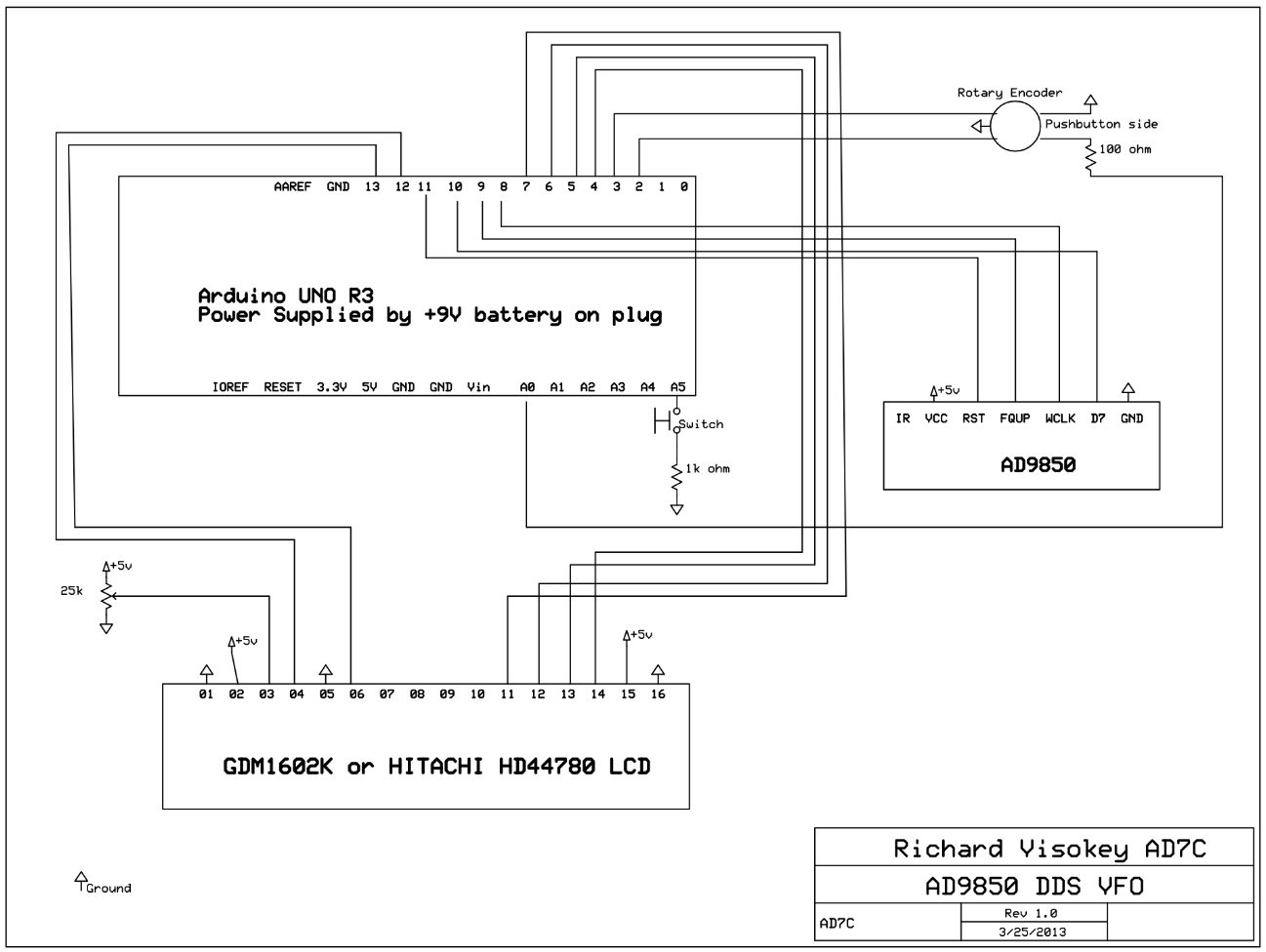
Circuit Diagram#
The circuit diagram for the variable frequency oscillator is shown below:
Building the Circuit#
To build the circuit, follow these steps:
Connect the AD9850 DDS module to the Arduino Uno as follows:
Connect the AD9850 module’s VCC pin to the Arduino’s 5V pin.
Connect the AD9850 module’s GND pin to the Arduino’s GND pin.
Connect the AD9850 module’s DATA pin to the Arduino’s digital pin 8.
Connect the AD9850 module’s W_CLK pin to the Arduino’s digital pin 9.
Connect the AD9850 module’s FQ_UD pin to the Arduino’s digital pin 10.
Connect the AD9850 module’s RESET pin to the Arduino’s digital pin 11.
Connect the 16x2 LCD display to the Arduino Uno as follows:
Connect the LCD display’s VCC pin to the Arduino’s 5V pin.
Connect the LCD display’s GND pin to the Arduino’s GND pin.
Connect the LCD display’s SDA pin to the Arduino’s analog pin A4.
Connect the LCD display’s SCL pin to the Arduino’s analog pin A5.
Connect the rotary encoder to the Arduino Uno as follows:
Connect the rotary encoder’s CLK pin to the Arduino’s digital pin 2.
Connect the rotary encoder’s DT pin to the Arduino’s digital pin 3.
Connect the rotary encoder’s SW pin to the Arduino’s digital pin 4.
Connect the power supply to the circuit. The AD9850 module requires a 5V power supply.
Programming the Arduino#
To program the Arduino Uno, you will need to install the AD9850 library. The library provides functions for controlling the AD9850 module and generating frequency outputs. You can download the library from the following link: Project Code
Once you have installed the library, you can upload the following code to the Arduino Uno:
Rotary Encoder Handler#
rotary.cpp
/* Rotary encoder handler for arduino. v1.1
 *
 * Copyright 2011 Ben Buxton. Licenced under the GNU GPL Version 3.
 * Contact: bb@cactii.net
 *
 * A typical mechanical rotary encoder emits a two bit gray code
 * on 3 output pins. Every step in the output (often accompanied
 * by a physical 'click') generates a specific sequence of output
 * codes on the pins.
 *
 * There are 3 pins used for the rotary encoding - one common and
 * two 'bit' pins.
 *
 * The following is the typical sequence of code on the output when
 * moving from one step to the next:
 *
 *   Position   Bit1   Bit2
 *   ----------------------
 *     Step1     0      0
 *      1/4      1      0
 *      1/2      1      1
 *      3/4      0      1
 *     Step2     0      0
 *
 * From this table, we can see that when moving from one 'click' to
 * the next, there are 4 changes in the output code.
 *
 * - From an initial 0 - 0, Bit1 goes high, Bit0 stays low.
 * - Then both bits are high, halfway through the step.
 * - Then Bit1 goes low, but Bit2 stays high.
 * - Finally at the end of the step, both bits return to 0.
 *
 * Detecting the direction is easy - the table simply goes in the other
 * direction (read up instead of down).
 *
 * To decode this, we use a simple state machine. Every time the output
 * code changes, it follows state, until finally a full steps worth of
 * code is received (in the correct order). At the final 0-0, it returns
 * a value indicating a step in one direction or the other.
 *
 * It's also possible to use 'half-step' mode. This just emits an event
 * at both the 0-0 and 1-1 positions. This might be useful for some
 * encoders where you want to detect all positions.
 *
 * If an invalid state happens (for example we go from '0-1' straight
 * to '1-0'), the state machine resets to the start until 0-0 and the
 * next valid codes occur.
 *
 * The biggest advantage of using a state machine over other algorithms
 * is that this has inherent debounce built in. Other algorithms emit spurious
 * output with switch bounce, but this one will simply flip between
 * sub-states until the bounce settles, then continue along the state
 * machine.
 * A side effect of debounce is that fast rotations can cause steps to
 * be skipped. By not requiring debounce, fast rotations can be accurately
 * measured.
 * Another advantage is the ability to properly handle bad state, such
 * as due to EMI, etc.
 * It is also a lot simpler than others - a static state table and less
 * than 10 lines of logic.
 */

#include "Arduino.h"
#include "rotary.h"

/*
 * The below state table has, for each state (row), the new state
 * to set based on the next encoder output. From left to right in,
 * the table, the encoder outputs are 00, 01, 10, 11, and the value
 * in that position is the new state to set.
 */

#define R_START 0x0

#ifdef HALF_STEP
// Use the half-step state table (emits a code at 00 and 11)
#define R_CCW_BEGIN 0x1
#define R_CW_BEGIN 0x2
#define R_START_M 0x3
#define R_CW_BEGIN_M 0x4
#define R_CCW_BEGIN_M 0x5
const unsigned char ttable[6][4] = {
  // R_START (00)
  {R_START_M,            R_CW_BEGIN,     R_CCW_BEGIN,  R_START},
  // R_CCW_BEGIN
  {R_START_M | DIR_CCW, R_START,        R_CCW_BEGIN,  R_START},
  // R_CW_BEGIN
  {R_START_M | DIR_CW,  R_CW_BEGIN,     R_START,      R_START},
  // R_START_M (11)
  {R_START_M,            R_CCW_BEGIN_M,  R_CW_BEGIN_M, R_START},
  // R_CW_BEGIN_M
  {R_START_M,            R_START_M,      R_CW_BEGIN_M, R_START | DIR_CW},
  // R_CCW_BEGIN_M
  {R_START_M,            R_CCW_BEGIN_M,  R_START_M,    R_START | DIR_CCW},
};
#else
// Use the full-step state table (emits a code at 00 only)
#define R_CW_FINAL 0x1
#define R_CW_BEGIN 0x2
#define R_CW_NEXT 0x3
#define R_CCW_BEGIN 0x4
#define R_CCW_FINAL 0x5
#define R_CCW_NEXT 0x6

const unsigned char ttable[7][4] = {
  // R_START
  {R_START,    R_CW_BEGIN,  R_CCW_BEGIN, R_START},
  // R_CW_FINAL
  {R_CW_NEXT,  R_START,     R_CW_FINAL,  R_START | DIR_CW},
  // R_CW_BEGIN
  {R_CW_NEXT,  R_CW_BEGIN,  R_START,     R_START},
  // R_CW_NEXT
  {R_CW_NEXT,  R_CW_BEGIN,  R_CW_FINAL,  R_START},
  // R_CCW_BEGIN
  {R_CCW_NEXT, R_START,     R_CCW_BEGIN, R_START},
  // R_CCW_FINAL
  {R_CCW_NEXT, R_CCW_FINAL, R_START,     R_START | DIR_CCW},
  // R_CCW_NEXT
  {R_CCW_NEXT, R_CCW_FINAL, R_CCW_BEGIN, R_START},
};
#endif

/*
 * Constructor. Each arg is the pin number for each encoder contact.
 */
Rotary::Rotary(char _pin1, char _pin2) {
  // Assign variables.
  pin1 = _pin1;
  pin2 = _pin2;
  // Set pins to input.
  pinMode(pin1, INPUT);
  pinMode(pin2, INPUT);
#ifdef ENABLE_PULLUPS
  digitalWrite(pin1, HIGH);
  digitalWrite(pin2, HIGH);
#endif
  // Initialise state.
  state = R_START;
}

unsigned char Rotary::process() {
  // Grab state of input pins.
  unsigned char pinstate = (digitalRead(pin2) << 1) | digitalRead(pin1);
  // Determine new state from the pins and state table.
  state = ttable[state & 0xf][pinstate];
  // Return emit bits, ie the generated event.
  return state & 0x30;
}
rotary.h
/*
 * Rotary encoder library for Arduino.
 */

#ifndef rotary_h
#define rotary_h

#include "Arduino.h"

// Enable this to emit codes twice per step.
//#define HALF_STEP

// Enable weak pullups
#define ENABLE_PULLUPS

// Values returned by 'process'
// No complete step yet.
#define DIR_NONE 0x0
// Clockwise step.
#define DIR_CW 0x10
// Anti-clockwise step.
#define DIR_CCW 0x20

class Rotary
{
  public:
    Rotary(char, char);
    // Process pin(s)
    unsigned char process();
  private:
    unsigned char state;
    unsigned char pin1;
    unsigned char pin2;
};

#endif
Once you have uploaded the code to the Arduino Uno, you can connect the circuit to a power supply and adjust the frequency using the rotary encoder. The frequency will be displayed on the 16x2 LCD display.
Video of the Project#
Conclusion#
In this project, we have built a variable frequency oscillator using the AD9850 DDS module and an Arduino Uno microcontroller. The oscillator can generate frequencies from 0 to 40 MHz with a resolution of 1 Hz. The circuit is simple to build and can be easily customized for different applications. The AD9850 DDS module is a versatile device that can be used in a wide range of projects, including signal generation, frequency synthesis, and waveform generation. By combining the AD9850 module with an Arduino microcontroller, you can create a powerful and flexible frequency generator for your electronics projects.